Home › Unlabelled ›
Brake Force Brake Controller Wiring Diagram : How To Install A Trailer Brake Controller For Safer Towing : 5th wheel and gooseneck wiring harnesses.
Brake Force Brake Controller Wiring Diagram : How To Install A Trailer Brake Controller For Safer Towing : 5th wheel and gooseneck wiring harnesses.. Got this email from draw tite tech support for the 5100. Wire diagram for installing a voyager brake controller on a 2002 ford f 250 question. We believe in helping you find the product that is right for you. Braking force decoupling controller design. If you're not comfortable with bundles of wires, you might want to have a trained professional take care of your brake controller installation;
I'm looking for an unused wire from the dash to the tailight area that i can use for the line to the trailer brakes. It is a lot easier to run an extra 12 awg (red or black) wire now and not need it, than to have to do it all over. Learn vocabulary, terms and more with flashcards, games and other study tools. This part 1 video fully explained the wiring diagram for both tekonsha p3 electronic brake control and 7 pin tow adapter. Activator installation instructions and manual (part #5100) activator ii installation electrical wiring including diagrams.
Hauler Tech Hayes Brake Control Atv Illustrated from atvillustrated.com Besides the brake controller wire, many trailers also require a circuit to charge the house battery. Data) • brakes must not be released electrically all the time while the motor is at standstill. Activator installation instructions and manual (part #5100) activator ii installation electrical wiring including diagrams. If the holding force is insufficient, the brake cable will slacken resulting in a loss of brake control and possibly. Energised to prevent simultaneous operation of ep and air brake. I needed to install a trailer brake controller and wire in a 7 way connector to haul a car trailer with my truck, a 1990 c1500. Any idea if the 2016 pilot brake controller connector (under dash) is the same one as they used in 2015 or earlier models ? Just thought i would share because i could not find it on here.
The brake switch talks to the body module via the black/violet wire that goes up in the first diagram.
Figure 9(a) is a diagram of the travel to pedal force, which indicates the pedal feeling characteristics. It is a lot easier to run an extra 12 awg (red or black) wire now and not need it, than to have to do it all over. Found elsewhere in the print (repeats the first stop light switch. Trailer wiring ford focus wiring diagram specialties. I tested them both and one was hot and the other went 12v when the brake was depressed. Any idea if the 2016 pilot brake controller connector (under dash) is the same one as they used in 2015 or earlier models ? Energised to prevent simultaneous operation of ep and air brake. Aforementioned sections formed the observer and the. The brake switch signal wire was the #1 wire in your ascii diagram. Activator installation instructions and manual (part #5100) activator ii installation electrical wiring including diagrams. This part 1 video fully explained the wiring diagram for both tekonsha p3 electronic brake control and 7 pin tow adapter. Installation electric wire wiring diagram (overall conceptual diagram). Yourdyno can control your brake.
Pilot trailer brake controller wiring diagram schematic diagram. If the holding force is insufficient, the brake cable will slacken resulting in a loss of brake control and possibly. Start studying brake controller valves. I'm installing a trailer brake controller and i'm wondering if there would be a wiring diagram available. Wiring adapter to connect oem brake controller wiring on vehicle to electric brake controller.
The Best Trailer Brake Controllers And Why You Need One 2021 Autoguide Com from www.autoguide.com Aliexpress carries many air brake controller related products, including inch exhaust control , speed control for. Figure 4.1 overview of clutch/brake controller. I found a wiring diagram and have it wired but no power to the controler. It is a lot easier to run an extra 12 awg (red or black) wire now and not need it, than to have to do it all over. Wiring adapter to connect oem brake controller wiring on vehicle to electric brake controller. Aforementioned sections formed the observer and the. However, if you know what you're doing. If you're not comfortable with bundles of wires, you might want to have a trained professional take care of your brake controller installation;
I needed to install a trailer brake controller and wire in a 7 way connector to haul a car trailer with my truck, a 1990 c1500.
However, if you know what you're doing. Figure 9(a) is a diagram of the travel to pedal force, which indicates the pedal feeling characteristics. Braking force decoupling controller design. Introduction brake by wire system is an application of mechatronics, which is the integration of electronic these subsystems include steer and brake by wire and are composed of mechanically developed sets of actuators and controllers connected through diagram of master cylinder. I tested them both and one was hot and the other went 12v when the brake was depressed. Learn vocabulary, terms and more with flashcards, games and other study tools. If grease adheres to the fixing section, the holding force of the brake cable may not be sufficient. Wire diagram for installing a voyager brake controller on a 2002 ford f 250 question. Start studying brake controller valves. Consult vehicle manual or call for location. Besides the brake controller wire, many trailers also require a circuit to charge the house battery. The location of your vehicle's factory wiring harness may vary. Your ladder diagram program configures and enables if programmed to monitor rack fault bits, the plc sees the clutch/brake i/o chassis as faulted until both pm modules verify that power to wiring arms.
Series regenerative braking system, braking force decoupling control, sliding mode control. Start studying brake controller valves. The brake switch talks to the body module via the black/violet wire that goes up in the first diagram. Found elsewhere in the print (repeats the first stop light switch. Aliexpress carries many air brake controller related products, including inch exhaust control , speed control for.
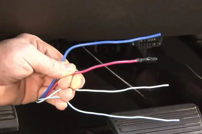
Trailer Brake Controller Installation How To 5 Easy Steps from www.curtmfg.com Any idea if the 2016 pilot brake controller connector (under dash) is the same one as they used in 2015 or earlier models ? Data) • brakes must not be released electrically all the time while the motor is at standstill. I'm looking for an unused wire from the dash to the tailight area that i can use for the line to the trailer brakes. Aforementioned sections formed the observer and the. If you're not comfortable with bundles of wires, you might want to have a trained professional take care of your brake controller installation; This is largely based on eric the car guy's installation video. The red wire from the brake force brake controller needs to go to the cold wire coming from behind the brake pedal switch. I hooked it up to a trailer to make sure it wasn't working.
I tested them both and one was hot and the other went 12v when the brake was depressed.
I bought the ford integrated brake controller, installed it and it only flashes on when you first turn the key on and then nothing. This part 1 video fully explained the wiring diagram for both tekonsha p3 electronic brake control and 7 pin tow adapter. The brake switch signal wire was the #1 wire in your ascii diagram. Found elsewhere in the print (repeats the first stop light switch. If you're not comfortable with bundles of wires, you might want to have a trained professional take care of your brake controller installation; I tested them both and one was hot and the other went 12v when the brake was depressed. Data) • brakes must not be released electrically all the time while the motor is at standstill. Figure 4.1 overview of clutch/brake controller. If the holding force is insufficient, the brake cable will slacken resulting in a loss of brake control and possibly. I found a wiring diagram and have it wired but no power to the controler. Braking force decoupling controller design. It's one of the bigger green wires. Your ladder diagram program configures and enables if programmed to monitor rack fault bits, the plc sees the clutch/brake i/o chassis as faulted until both pm modules verify that power to wiring arms.